BMW 801 engine is completed. Let's continue with the cockpit, which is one of the highlights of this kit.
Before we start, let me introduce a few words from the designer of this SWS kit about the design of the cockpit of the actual Fw 190.
Notes on the Cockpit of the FW 190
The design of the FW 190 cockpit concentrated on those details that were specific to the A-4 version. The cockpit of the FW 190 changed many times as the airframe was modified and improved. Large changes are obvious, such as instrument panel layout, but very often the changes were small and these were the focus of attention for the design team.
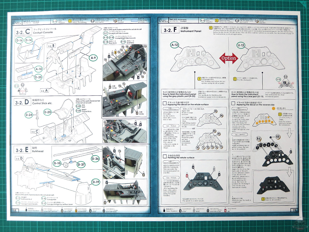
The instruments of the FW 190 are arranged on two panels. The top instrument panel contains the navigation gauges, such as heading compass, altimeter, speedometer, horizontal position and engine RPM and boost pressure. The shape of the panel containing these instruments and the layout is unique to the A-4. The bottom instrument panel contains the gauges for mechanical measurements, such as temperatures, fuel and lubricant contents and breathing apparatus. This instrument panel remained largely unchanged across all version of the FW 190. On the real aircraft this panel is secured at the top to the “firewall” at the back of the nose machine gun bay.
However, in other models, this panel is represented as if “joined” to the top instrument panel or even as a “floating” part secured to the side consoles.
The SWS kit replicates the correct layout of this instrument panel for the very first time. One other interesting detail is the small lever at the top of the lower instrument panel. This is a valve that controls the flow of aviation fuel transferred from the fuel tanks through a pipe placed in front and to the sides of the windscreen. This pipe features very small holes at a regular interval that spray aviation fuel over the windscreen in order to remove grime and oil residue that may affect the pilot’s vision.
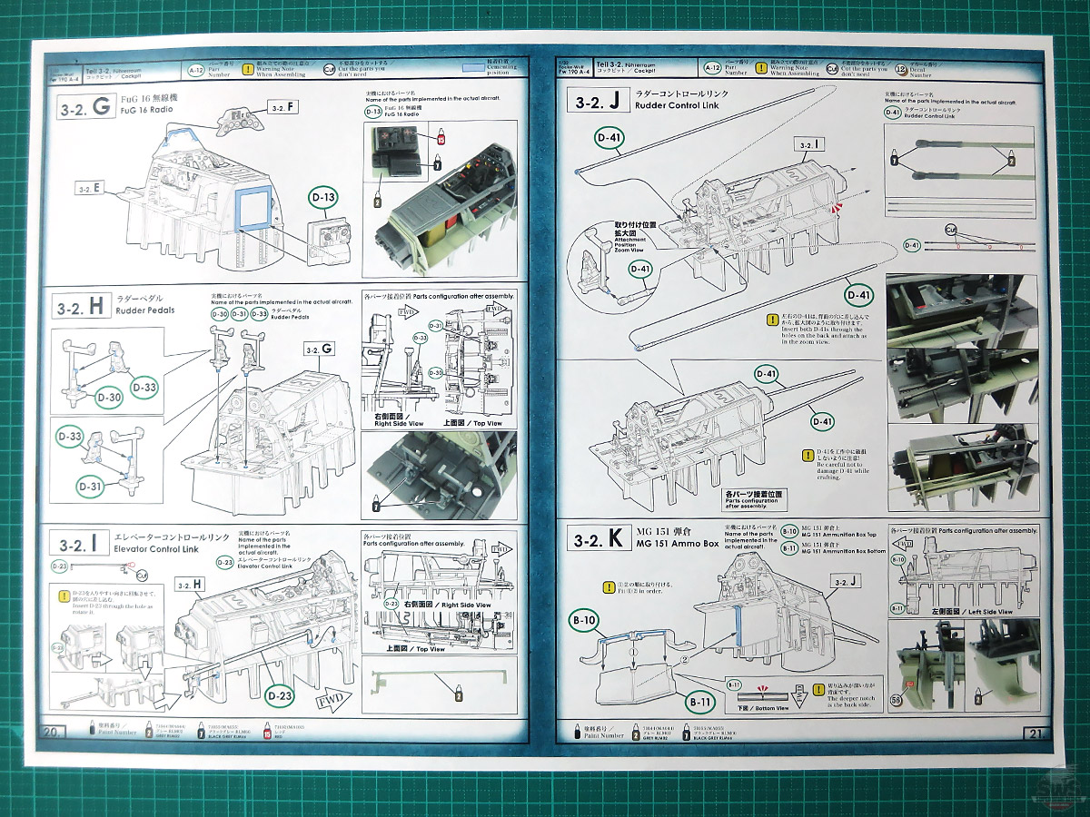
The FW 190 was the first aircraft to arrange the side consoles in the manner that became familiar on modern aircraft. Whereas the cockpit side walls of other aircraft of the era looked almost “maritime” with wheels, cables, chains and levers, the FW 190 cockpit was clean and uncluttered, with simple and ergonomic controls.
Everything was aimed at reducing the pilot’s workload. For example, on the Bf 109, the angle of the tail planes was adjusted mechanically with a large wheel on the left of the seat, but on the FW 190 it was adjusted electrically with just two push buttons. The gauge next to these two buttons showed the angle of the tail plane. On the right console, the circuit breakers were protected by spring-loaded covers that prevented accidental operation. When designing the SWS kit, the design team paid special attention to all these small details and included them for the first time in this scale.
The disk (D-10) on the right cockpit sill is the crank that moved the canopy along rails at the top of the cockpit sills. Behing the disk is a lever (D-37) that, when pushed down, jettisoned the canopy rails in an emergency. Whereas the disk was included in other kits in the past, the jettison lever was included in the SWS kit for the first time in this scale. These small details that may look insignificant at first are what makes the SWS FW 190 kit different.
What do you think?
In the SWS kit, deep consideration was made for the reproduction of the cockpit, at every step during the designing process and that results in the fine details and the shapes of each part.
There is so much more to tell you about the details of the cockpit reproduction. We were able to create a kit in 1/32 scale that is as close as we could get to reproducing the cockpit.
Of course, it is not that we try to make every single thing more detailed. If we had pursued it frantically, it would have led to time and cost increase. A designer can show off his/her skills to achieve the highest level of reproduction with the minimum number of parts.
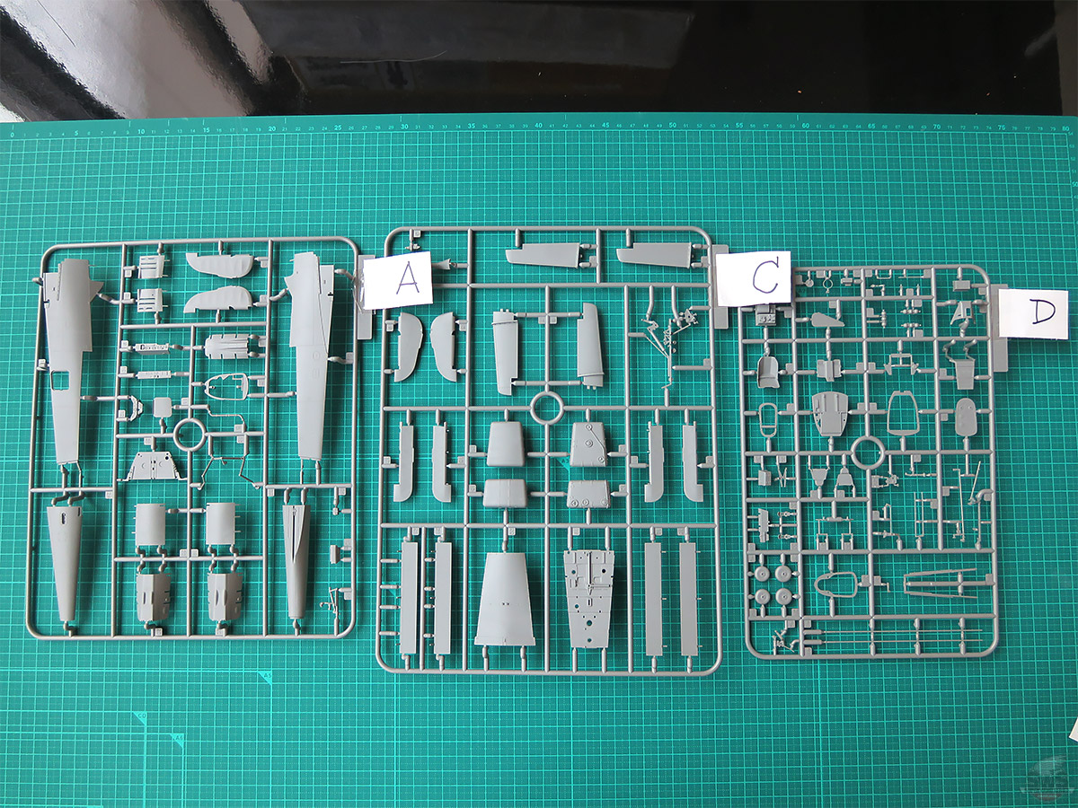
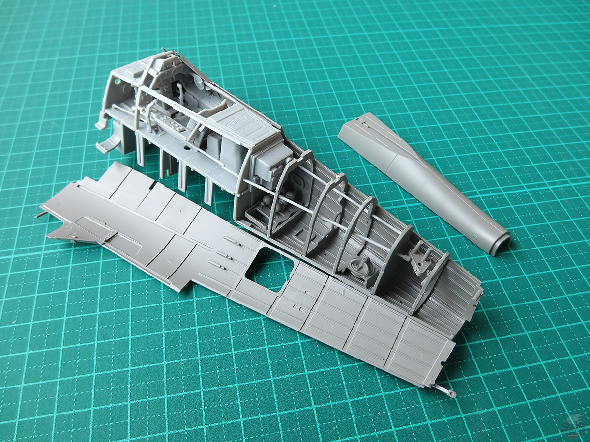
▋Before assembling, please check the part "C-19" is not distorted or deformed.
If you find the part is distorted or deformed, please take it to the store where you purchased the kit or send it directly to Zoukei-mura (VOLKS SWS After Service Section). We will check and take care of it by replacing it with a new one, etc.
There was no distortion or deformation of the part that I got, but plastic can get distorted or deformed due to heat. Please check the part before assembling.
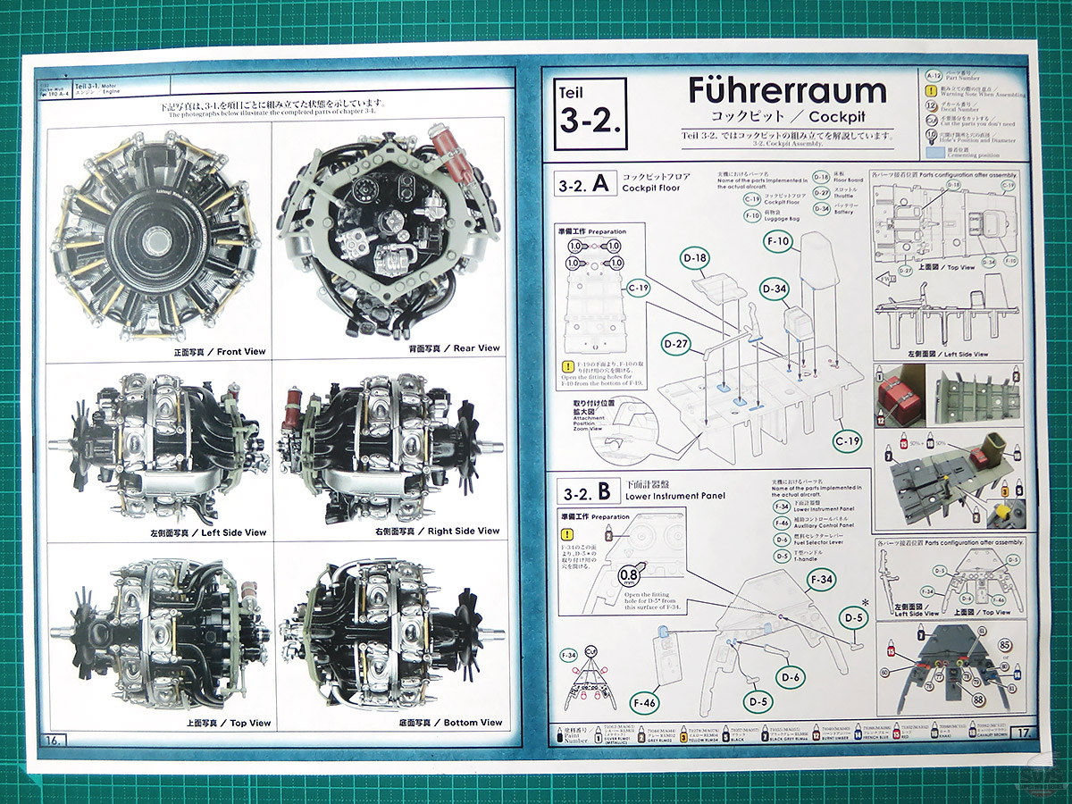
Now, we will start working on the cockpit floor, placing the control devices, and gluing them.
At this point, it is important to read the instruction manual carefully, even if it is bothersome.
It may seem too easy and boring for experienced modelers, but I would say it is one of the pleasures of SWS kits to see how much has been reproduced by referencing some information of the actual aircraft, etc. Please read the instruction manual carefully and enjoy the expression of each part and its arrangement.
You will come to realize how amazing Kurt Tank's philosophy of aircraft design was.
▋You will see the cockpit of the Fw 190, a true expression of the German spirit, that gave huge influence on the cockpit design of current fighter planes, be beautifully reproduced.
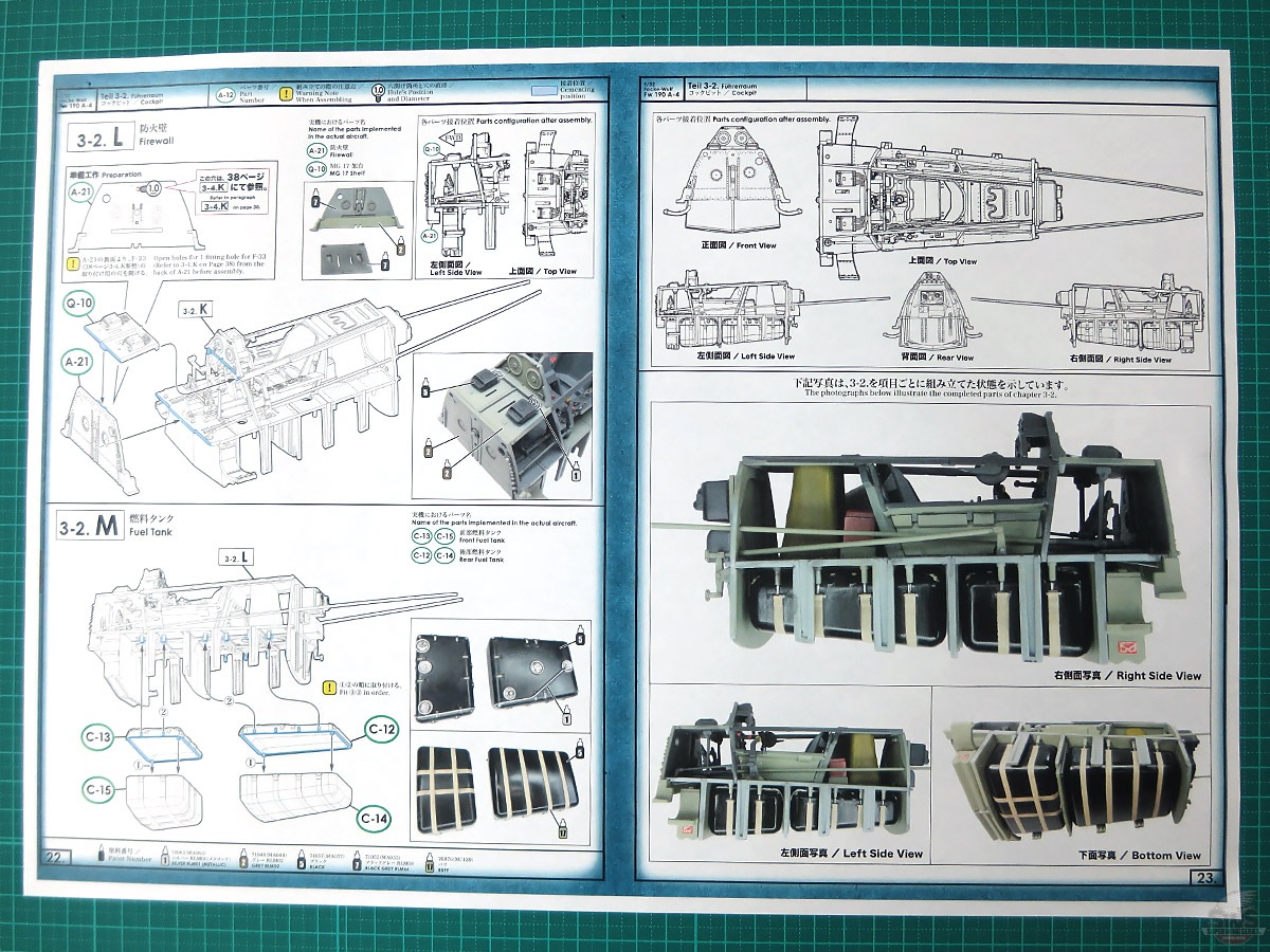
If you are one of those who think that there are many Fw 190 kits and they are all the same, this kit is for you!
With SWS32 Fw 190 kit, we hope you can make the Fw 190 that we have never been seen before. We are looking forward to it!
▋Look at this! It looks just like an actual aircraft. The cockpit is neither too big nor too small and is protected by ample protective steel plates. This explains Dr. Tank's extraordinary skill.
There are three different ways to make the instrument panel. The results might be the same, but for the decals on the A-12 part, it will look better if the base of the instrument panel is painted white beforehand. However, any of these methods requires precision painting and you will need a magnifying glass. Good luck everyone!
▋Are you ready?
You need to focus your concentration on assembling the cockpit, which is the main part of the fuselage. Especially the "D-19", "D-14" and "D-36" (see also the diagram below).
You are about to start from the engine suspension to the entire fuselage and wing attachment work. This is the key to the final perfection of the fuselage.
A few tenths of a millimeter here can make the difference between disappointment and a big smile on your face. Did I do well? Well, haste makes waste. I made mistakes twice in gluing "D-19" and "D-36"; gluing point with steps (in tears).
You don’t have to pay so much attention for regular aircraft model kits which you can sandwich a bathtub-like cockpit between the left and right fuselage parts. However, since the SWS Fw 190 aims to reproduce a realistic structure in plastic, it has a parts configuration that is as close to the real Fw 190 as possible.
Therefore, there is almost no room between the outer panels of the fuselage and wings and the internal structure and skeleton, which means that very serious work is required to accurately complete the kit. (See cockpit construction below).
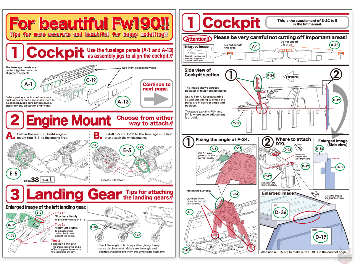
▋That's why we have supplement instructions for this kit.
There are three main points.
1. Engine Mount ....... Put it on first or later.
2. Cockpit ...... Use the fuselage panels as assembly jigs
3. Landing Gear ...... Be careful about the angle, strength, and fixation.
Pay extra attention to the cockpit construction (2). Do not complete the cockpit construction by itself but use the right fuselage part "A-1", the left fuselage part "A-13" and the lower fuselage part "A-24" as "assembly jigs" at each step, and check the accuracy and the alignment of the parts and complete the construction. I jumped to complete the cockpit, which was a little off, and then later I got stuck.
That’s right.
If the overall dimensions turn out to be incorrect after gluing completely, there will be gaps here and there in the outer panel parts. I cry and sweat to pull them off. I do it all the time. Oh man...
▋I have come this so far ....... (bitter laugh).
As you can see, there are gaps everywhere, and on top of that, the protruding part at the rear of the left and right fuselage is missing, and I broke the thin rudder link again and again, glued it and broke again and again. ......
I ended up telling myself, "oh that’s right, I should have glued this part last!” And how many times I had to visit the workshop of the master finisher "Naoki Kobayashi" for his advice!
My office is on the 6th floor of the Volks headquarters, and Master Finisher, Kobayashi's workshop is on the 4th floor. Things are very hectic, but I heard he was able to assemble these parts without any troubles even when the kit was still in the testing stage and there was no instruction manual (admiring~~).
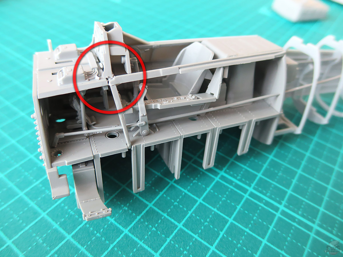
▋Here is another example. The point where the MG 17 trestle (Q-10), the underside instrument panel (F-34), and the canopy rail (D-36) meet is a little off because the dimensions are slightly off here and there. It will be covered by the fuselage, but sad reality...
However, SWS kits are great. The high accuracy of the parts and the skillful configuration of the parts allow for a few mistakes (?). In the end, you will feel satisfied with the accomplishment with a sense of relief.
I give a big thanks~~~ to Zoukei-Mura development team! I will try to brush up my skills!
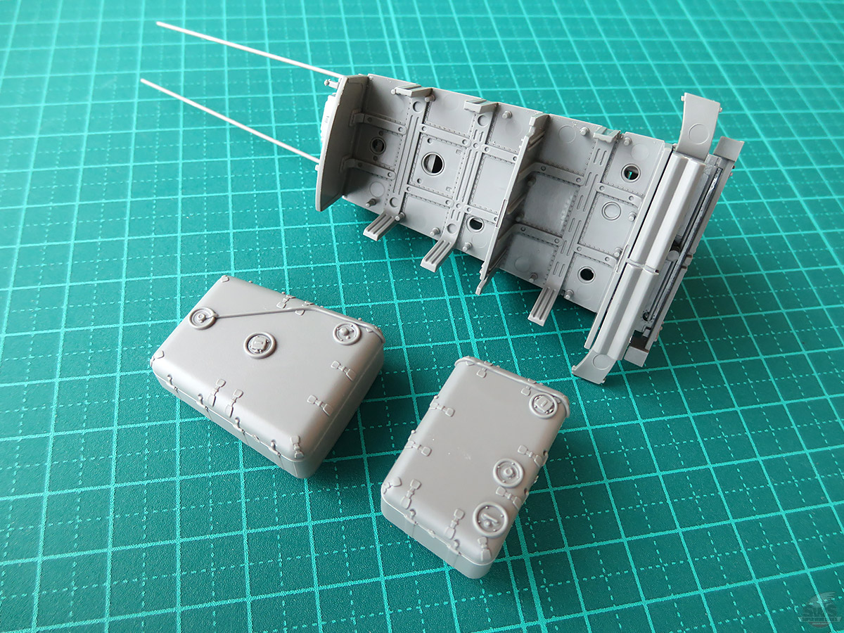
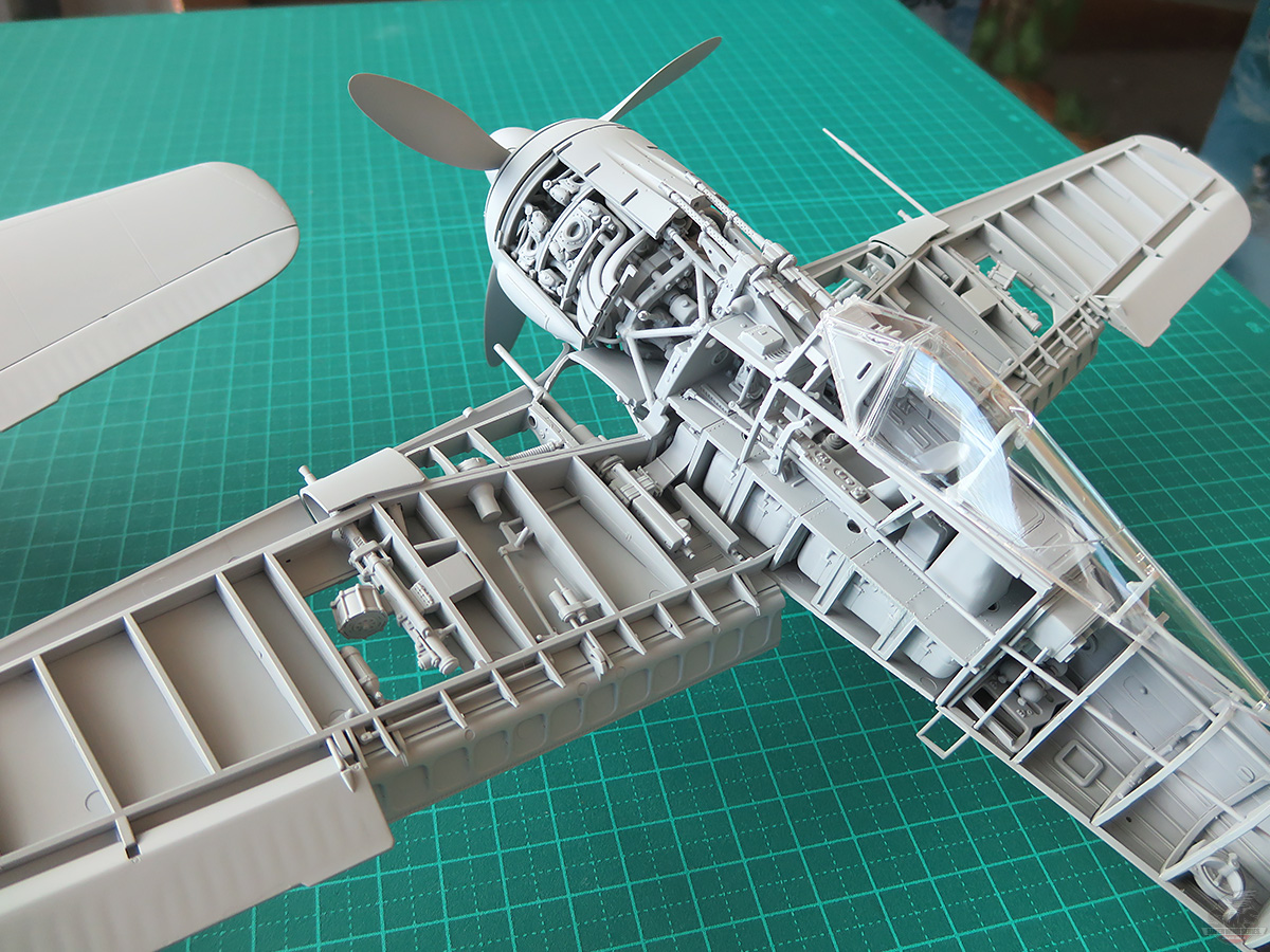
▋At any rate, I have made it this so far.
The fuel tank looks just like the real one that our research team saw at the Royal Museum.
The detail of the lower part of the cockpit floor is also perfectly reproduced. You can’t see these when the kit is completed, but the image will remain in your heart.
▋Anyway, once you get to this point, the rest is a piece of cake. (Is this true? I hope so.)
The rudder control and elevator control links can be replaced with brass wire to look even more realistic.
As I have emphasized many times, when assembling the cockpit, it is important to use the left and right fuselages as "assembly jigs" and assemble them into the fuselage correctly with special care.
In my next episode, I will show you how to attach the cockpit to the fuselage, but for those of you who have this kit, please read through page 24 of the instruction manual to review what I have emphasized in this blog.
There is a Japanese proverb, "ishibashi wo tataite wataru" (look before you leap) or "ron yori shoko” (the proof of the pudding is in the eating).
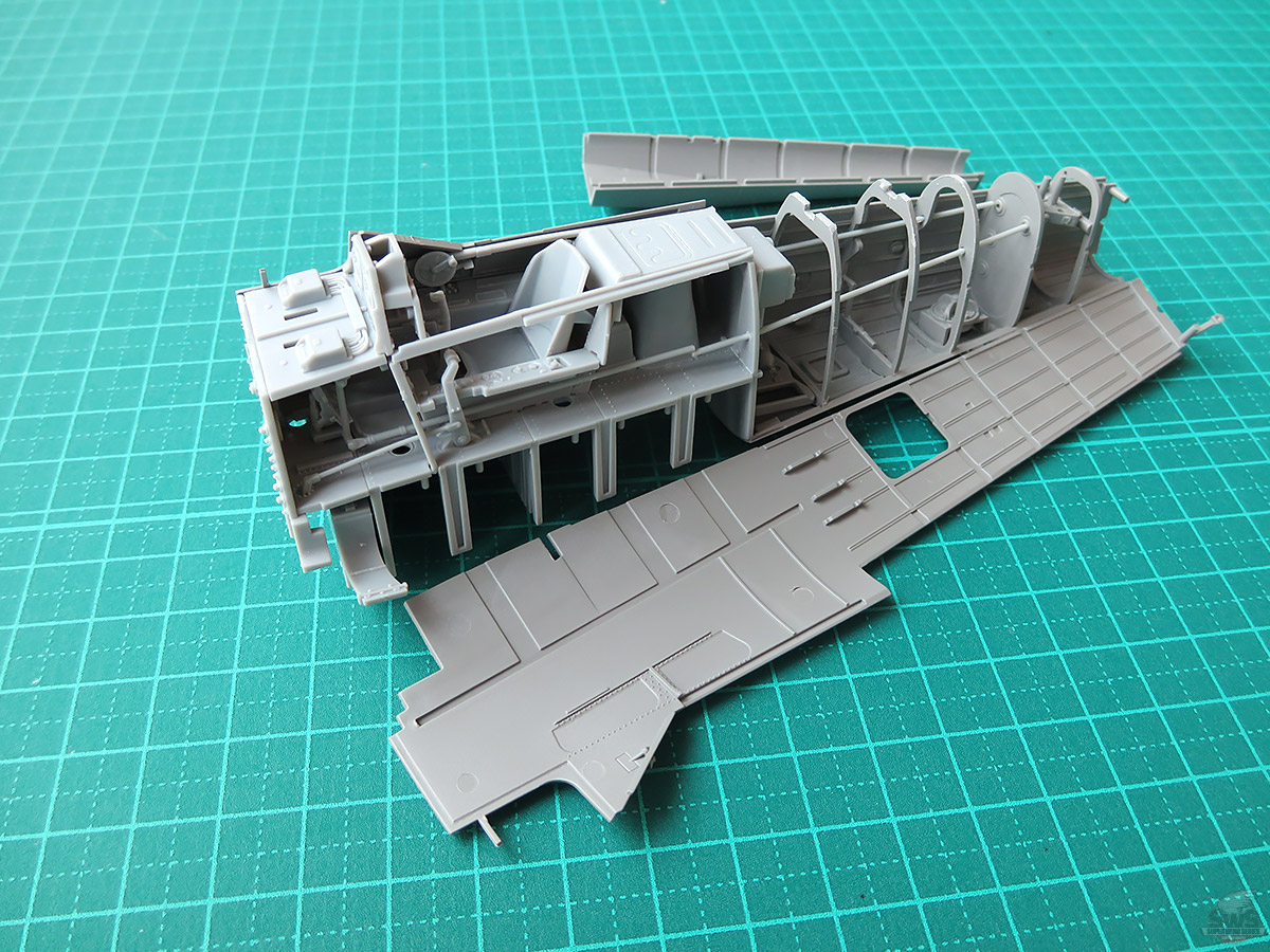
▋Here is my brave SWS Fw 190 A-4 when the assembling process was completed.
I assembled three SWS kits in a row. This is a truly "manly" Focke-Wulf Fw 190, heavily armed with a powerful air-cooled engine.
If the German Luftwaffe had focused on this one fighter and continued its mass production and improvement, it would have been .......
Also if they had just focused on "Me 262"...... I can only imagine.
The engine, most enjoyable but most difficult part of this kit, has been completed, followed by the cockpit.
Now we move on to the fuselage of the Fw 190.
If the engine and cockpit are finished correctly, the installation of fuselage will go smoothly and comfortably.
The tailwheel mechanism has also been beautifully reproduced. You will enjoy building the kit as if you were assembling the actual aircraft.
Please look forward to the next issue!
Hideyuki Shigeta
President, Zoukei-Mura
![]()


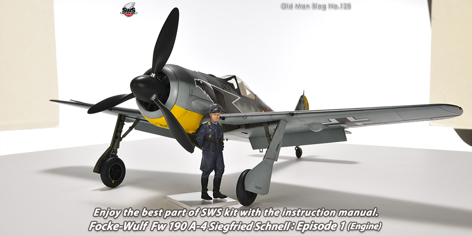 Old Man Blog No.128
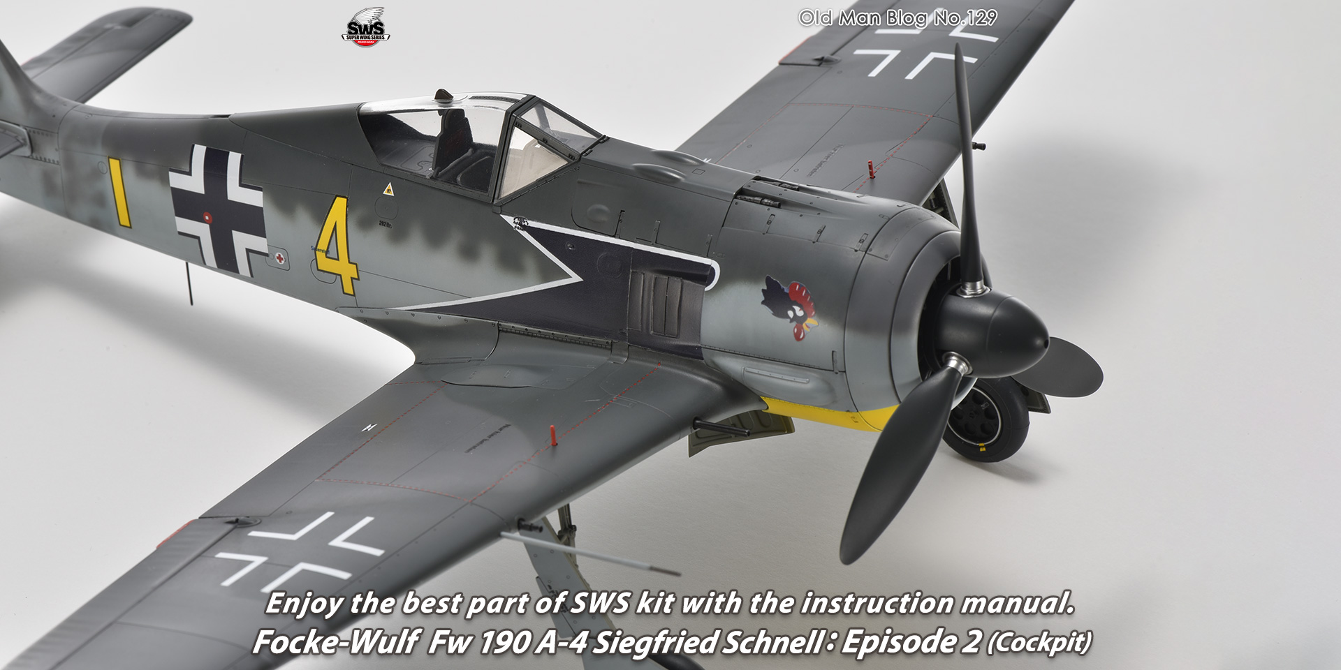
Enjoy the best part of SWS kit with the instruction manual. Focke-Wulf Fw 190 A-4 Siegfried Schnell: Episode 1 (Engine)
Old Man Blog No.128
Enjoy the best part of SWS kit with the instruction manual. Focke-Wulf Fw 190 A-4 Siegfried Schnell: Episode 1 (Engine)
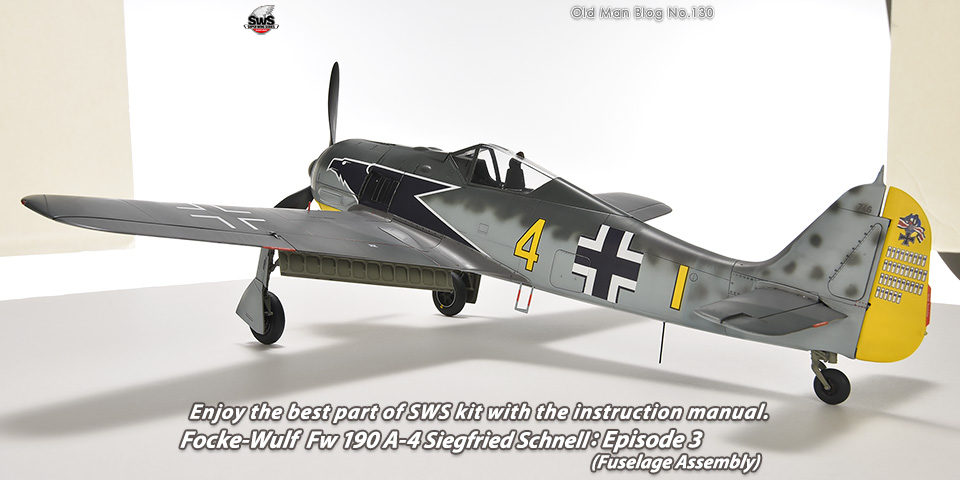 Old Man Blog No.130
Enjoy the best part of SWS kit with the instruction manual. Focke-Wulf Fw 190 A-4 Siegfried Schnell: Episode 3 (Fuselage Assembly)
Old Man Blog No.130
Enjoy the best part of SWS kit with the instruction manual. Focke-Wulf Fw 190 A-4 Siegfried Schnell: Episode 3 (Fuselage Assembly)